ediabaslib
Replace ELM327 BT V1.5 HW: V01_M_V2.3 adapter firmware (or equivalent)
This chapter describes how to replace the ELM327 BT V1.5 HW: V01_M_V2.3 adapter PIC18F25K80 firmware and YC1021 BT settings.
Requirements:
- ELM327 BT V1.5 HW: V01_M_V2.3 adapter (or equivalent)
- EZP2010/TL866II Plus/CH341A Eeprom programmer with SOIC8 (150mil) programming clip
- PicKit 3/4 (to program the PIC18F25K80)
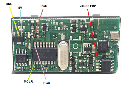
ELM327 BT V1.5 HW: V01_M_V2.3 board connections:
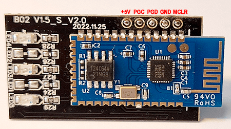
ELM327 BT V1.5 HW: V1.5_S_V2.0 board connections:
Step1: Program the YC1021 BT settings
- Connect your EZP2010 or TL866II Plus or CH341A Eeprom programmer clip on to the SOIC8 (150mil) 24C32 / 24C64 eeprom chip, take note of orientation (red wire of clipon goes to red annotated 24C32 pin1)
- Do a full read with eeprom powered from programmer (do not apply power from obd side).
It’s recommended that you disconnect VCC pin 8 of the 24C32 chip first!
It may take a few read tries to get the full dump correctly, if the first 0x80 bytes only contain 0xFF your read is incorrect. - There are two EEPROM layout variants with an data offset of 0xB (original files
original_v1_.binandoriginal_v2_.bin) - EEPROM 24C32 layout variant 1 / 2:
- BT address: 0x0F93 / 0x0F88 (6 bytes, normally keep unchanged)
- BLE address: 0x0F99 / 0x0F8E (6 bytes, normally keep unchanged)
- PinCode: 0x0F9F / 0x0F94, 1 byte length (max 15) and 15 byte PIN ASCII chars
- BT 2.x name: 0x0FAF / 0x0FA4, 1 byte length (max 32) and 32 byte BT name ASCII chars
- BLE name: 0x0FD0 / 0x0FC5, 1 byte length (max 24) and 32 byte BLE name ASCII chars
- BaudRate: 0x0FF0 / 0x0FE5 (2 bytes, low byte first); default value: 0x04E2 is 38400 baud (for
defaultPIC firmware), change to 0x01A1 for 115200 baud (fordef115200oryc1021firmware)
- EEPROM 24C64 layout variant:
- BT address: 0x18E3 (6 bytes, normally keep unchanged)
- BLE address: 0x18E9 (6 bytes, normally keep unchanged)
- PinCode: 0x18EF, 1 byte length (max 15) and 15 byte PIN ASCII chars (for some unknown reason some have 0000 but the adapter accepts only 1234)
- BT 2.x name: 0x1900, 1 byte length (max 32) and 32 byte BT name ASCII chars
- BLE name: 0x1920, 1 byte length (max 24) and 32 byte BLE name ASCII chars
- BaudRate: 0x1940 (2 bytes, low byte first); default value: 0x04E2 is 38400 baud (for
defaultPIC firmware), change to 0x01A1 for 115200 baud (fordef115200oryc1021firmware)
- Optionally you may use the preconfigured settings file
modified_v1.binfrom the latest binary, if it’s exactly matching your device firmware. This is not recommended! - Write the changed binary back to the 24C32/24C64A eeprom (again powered from programmer, not from obd side).
Step2: Program the PIC18F25K80
- Connect your PicKit 3/4 to MCLR, PGD, PGC, GND (Vss) and 5V (Vcc) (take care, do not apply power from PicKit 3/4)
- Power the Elm327 adapter (from obd side)
- From subdirectory
CanAdapterElmselect eitherdefault(baudrate 38400),def115200(baudrate 115200) oryc1021firmware (recommended for non standard LED allocation) (baudrate 115200), always useCanAdapterElm.X.production.unified.hexfor this first upload - Flash the selected firmware to the PIC18F25K80
Step3: Testing
- Power the Elm327 adapter
- Connect to XXYYZZ BT device and pair with it (standard pincode: 1234)
- Connect to the COM port assigned to your BT device
- When sending strings to the adapter you should at least get an echo from the adapter, otherwise there is a problem with the connections.
You could test reading the ignition pin with the following command (hex values):
82 F1 F1 FE FE 60
The response is (additionally to the echo):
82 F1 F1 FE <state> <checksum>with state bit 0 set to 1 if ignition is on.

